Five-Minute Schematic and Simulation
This tutorial will give you a taste of how quickly you can put together a circuit with full simulation. These tutorials are intended only to introduce you to LogicWorks features. For complete details on any subject, see the reference manual that comes with LogicWorks.
Tutorial Manual Format
In the following tutorial sections text with a square,
- like this,
provides step-by-step instructions for achieving a specific goal. Other text provides background and explanation of the actions being taken.
Starting LogicWorks
Start the :LogicWorks program by double-clicking on its icon.
Once the program has started, you will be looking at a screen like this:
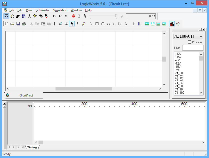
The circuit window is your view port onto the circuit diagram, which you will manipulate using the various drawing tools. The smaller panel at the bottom of the screen will be used by the program to display a timing diagram of the signals in your circuit, as well as other outputs generated by your circuit. Either of these windows can be moved or resized by the usual methods to suit your needs.
Placing a Device
The Parts Palette shows a merged list of all parts in all open libraries. Libraries can be opened and closed manually by using the Parts Palette pop-up menu’s Open and Close commands, or any collections of libraries can be opened automatically at start-up by placing them in the Libs directory. The Parts Palette appears as follows

The list of open libraries can be changed manually by doing either of the following:
- Click on the File Menu and select the Libraries submenu; then choose the New Lib or Open Lib commands as needed.
- Right-click on the Parts Palette , and use the same set of library commands that appears in that menu
Any collection of libraries can be opened automatically at start-up by modifying the INI file. The procedure is described in more detail in the LogicWorks Reference manual provided in electronic form with the software.
- Locate the Filter text box on the Parts Palette. Type the text 164 into this box. This step will reduce the parts list to only items containing that text.
- Locate the part 74_164 in the parts list, and double-click on it.
- Move the cursor back into the circuit window. The cursor on the screen will now be replaced by a moving image of the selected symbol, in this case an 8-bit shift register.
The numbered devices in this library are generic 7400-series types. The labelling and simulation characteristics can be adjusted to match the various 7400 families on the market.
- Position this image somewhere near the centre of the circuit windows , and click the left mouse button. A permanent image of the device will now stay behind in that location, and the cursor image will continue to follow the movement of the mouse:

More devices of the same type could be created at this point, but in this example we wish to select another symbol:
- Press the space-bar to return to Point mode. Notice that you can click and drag the device that you placed to any desired new position.
- Move again to the Parts Palette, and this time double-click on the XNOR-2 type. (You might need to change the text in the “Filter box, if you used it in a previous step). Once you move outside of the Parts Palette, the cursor will immediately change to match the new symbol.
The XNOR-2 and the devices in the Simulation Gates, Simulation Logic, and Simulation I/O libraries are called primitive types because they have built-in simulation models in LogicWorks. Other devices such as those in the 7400 library, are called sub-circuit types , because their simulation models are made up of primitives. If LogicWorks is being used only for schematic entry, it is also possible to make symbols with no simulation function.
- Place one of the Exclusive-NOR gates adjacent to the 164 device so that the pins just touch., and click once to anchor the device.

- Press the space-bar to return to Point mode.
Whenever you place devices or signal lines so that they touch, you will notice that the signal lines flash briefly. This indicates that a logical connection has been made. You do not need to explicitly request a connection.
Moving a Device
- Point at the Exclusive NOR gate, and click and drag to the right. While you hold the left mouse button, you can drag the device to any desired new position. Note that any signal lines attached to the device are adjusted continuously to maintain connection.
- Position the gate to the right of the 164 device so that it appears as follows:

Drawing Signal Connections
- Attach a connection to the output of the gate by positioning the pointer near the endpoint of the pin and dragging away to the upper left

- Notice that two lines at right angles will follow your mouse movements to connect the starting and ending points.
While moving the mouse, try pressing the CNTRL or ALT key, and note the different line-routing methods available. Click the left mouse button once to anchor th signal line. For details on these line-routing modifier keys, see the section on signal-line editing in the LogicWorks reference manual provided in electronic form with this software.
- Leave a right-angle line attached to the gate as follows:

- Extend this line to connect to the B input of the 164 by clicking at the line endpoint where you left off, dragging the line to the B input, and releasing the mouse button:

Add a connection to pin A by clicking at the end of the pin, dragging the line down until it touches the signal line, and then releasing the mouse button:

Notice that an intersection dot appears automatically whenever three or more lines intersect.
- Try repositioning a line segment by clicking and dragging anywhere along the length of the segment except at a corner or intersection.
Binary Switch Input Device
- Return to the Parts Palette and select a Binary Switch device.
- Place it as shown on the following diagram.

- Press the space-bar to return to Point mode.
- Try clicking on the switch. Notice that it changes between the 0 and 1 states.
In order to move a switch, you must first select it by holding the SHIFT key while clicking on it. This is necessary because the switch has a special response to a normal mouse click.
The devices in the Simulation I/O library can be used to actively control and observe the simulation right on the schematic. Each of these devices responds immediately to changes in the simulation in progress. The Hex Keyboard device is similar to the switch except that it operates on four lines at once.
Clock Generator Device
- Select a Clock device and place it on the diagram just below the switch.
- Press the spacebar to return to Point Mode
- Route wires from the switch and clock to the 164, as shown in the following diagram(remember to try using the CTRL and ALT keys to route the wires):

While you have been working on the diagram, the LogicWorks simulator has been running continuously, simulating the effects of the new connections that are being made. So far, though, we have not asked it to display any results. This is done either by placing probes on the diagram or by displaying signals in the Timing window.
Naming a Signal
- Click on the text tool in the Tool Palette. The cursor will then change to a pencil shape, which will be used to select the item we want to name.

The text cursor is used to name devices and signals, to apply pin numbers to device pins, and to add free-text notations to the diagram.
- Position the tip of the pencil anywhere along the length of the line running from the clock device, and click. A blinking insertion marker will appear:

- Type the name CLK on the keyboard and then press the ENTER key or click the left mouse button once outside the text box.

- Return to Point mode by clicking the arrow icon in the Tool Palette. Note that the name can be dragged to any desired position.
- Click once on the Binary Switch to change it to the logical 1 state.
The Timing Window
You will immediately see the Timing window come to life, with the displayed values on the CLK line:

By default, any named signal is shown automatically in the Timing window, although you can change this setting by using the Add Automatically command in the Simulation menu.
- Again using the text cursor, name the two data lines from the shift register and the output line from the gate as follows:

The simulated output from these lines will immediately appear in the Timing Window.
Simulation Controls
Click on the <> and >< buttons, and observe that they affect the timing scale of the Timing window.

The display resolution can be adjusted over a wide range of time values to suit the displayed data.
- Select the Timing Window item in the View menu. You will notice that the Timing window disappears and the current time indicator in the Simulation palette advances much more quickly.
- Select the Timing Window command again
 or use the corresponding
  button to re-enable the display
 - Click on the ( )Reset button, and notice that the simulation restarts at time 0.
- Adjust the speed slider control in the Simulator toolbar, and notice the simulation slows.
- Click repeatedly on the Step (
 ) button, and observe that the simulation proceeds one step at a time.
 - Click on the Run button in the Simulator toolbar.
Note: The Step button advances the simulation to the next time at which there is some circuit activity, not necessarily just one time unit. The size of the step will depend upon the circuit.
Probe Device
- Select the Binary Probe type from the Parts Palette.
- Place a probe so that its pin contacts a signal line to view the simulation value on that line:

As the simulation progresses, the values on all probes are updated immediately. A similar device, the Hex Display, is also available to show groups of lines in hexadecimal. These simulation devices can be flagged to indicate that they are not a real part of the finished product and should not be included in any netlists or bills of materials.
Setting Device Parameters
- Click in the window, but away from any circuit objects. This deselects everything.
- Click on the XNOR gate to select it.

- Select the simulation Params command in the Simulation menu.
- Use the controls in this box to increase the propagation delay in the device to 5 ns:

The Simulation Params command is used to view and set delays associated with devices and pins. Pin delays normally default to zero, but can be used to fine-tune the delays for different paths through a device.
- Click on the OK button.
Device Delay on the Timing Window
Notice that the altered device delay immediately affects the simulation. You will see an increased delay between the clock reference lines and the changes in the FEEDBCK signal:

Interacting with the Simulation
- Try clicking on the switch hooked to the CLR input:

Notice that it changes state and immediately affects the displayed simulation results.
Save the Design
Click the Save button(![]() ) to save your circuit so you can continue with it later.
) to save your circuit so you can continue with it later.
This ends the Five-Minute Schematic and Simulation tutorial section.
The next tutorial is Schematic Editing.